Prepare X-Nucleo – STEP200
STEP200 (X-NUCLEO-IHM02A1)
| Arduino | (Ethernet) | Default | Modified | Firmware | Note |
|---|---|---|---|---|---|
| D0 | |||||
| D1 | |||||
| D2 | |||||
| D3 | SCK | LED | LED | #1 | |
| D4 | SD CS | STBY/RST | SD CS | SD CS | #2 |
| D5 | |||||
| D6 | |||||
| D7 | |||||
| D8 | STBY/RST | RST - L6470 | #2 | ||
| D9 | |||||
| D10 | CS | CS - W5500 | |||
| D11 | MOSI | MOSI | MOSI - L6470 | ||
| D12 | MISO | MISO | MISO - L6470 | ||
| D13 | SCK | SCK - L6470 | #1 | ||
| A0 | |||||
| A1 | |||||
| A2 | CS | CS | CS - L6470 | ||
| A3 | |||||
| A4 | |||||
| A5 | |||||
| MOSI | MOSI | MOSI - W5500 | SPI pin header | ||
| MISO | MISO | MISO - W5500 | SPI pin header | ||
| SCK | SCK | SCK - W5500 | SPI pin header |
1: Move L6470 SCK
Initially, the CS pin of the L6470 on the IHM02A1 is D3, but let's move it to D13 to adapt the Arduino SPI pin layout. Remove the 0Ω resistor at SB34 on the IHM02A1, then move it to the SB12 pad. I think this process would be difficult without two soldering irons. Or you could smash the SB34 resistor with a cutting plier and solder the SB12 pad to short it.
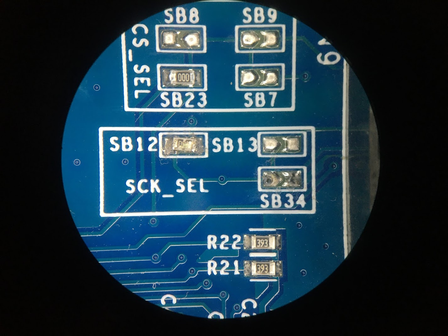 In this photo, I struggled to reattach the removed resistor to the SB12, and it became dirty.
2: SD CS and L6470 STBY/RST
As in the case of STEP100, the CS pin of the SD card and the STBY/RST pin of the L6470 are assigned to the same D4, so let's cut the legs on the IHM02A1. However, the cut STBY/RST pin is required to boot up the L6470s, so reassign it to another pin using a jump wire. You can use any unused pins, but we will use D8 here. Connect D4 and D8 with a jump wire on the X-Nucleo pin socket.
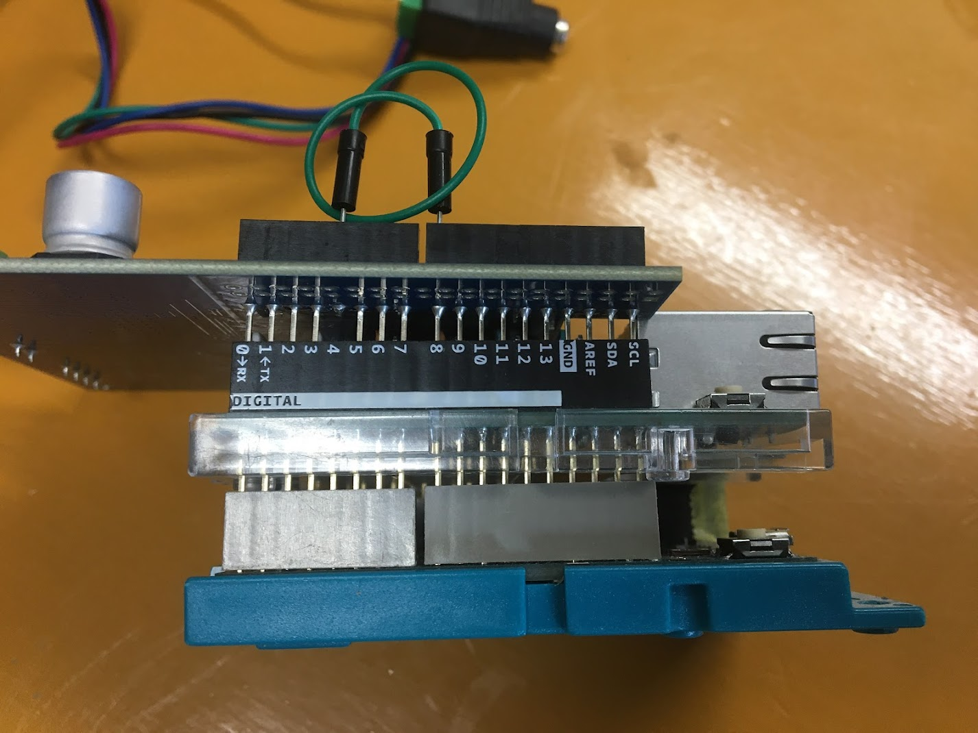 A view of the X-Nucleo stacked on top of the Arduino and Ethernet Shield. Now the X-Nucleo's D4 is reassigned to D8.