Homing and position management
Stepper motor and homing
When the system powers up, it doesn't know where the motor is currently positioned. It could be pointing to various directions depending on the timing of the last time the system was shut off.
Also, if the stepper motor receives exceeding external force, the step will slip out of alignment (stall). If this happens, the motor will continue to work with an unknown offset between the expected position and its actual.
Therefore, applications that have position or orientation must use sensors to detect a reference position on startup or periodically while it is active. This action is called homing.
Switches and Sensors
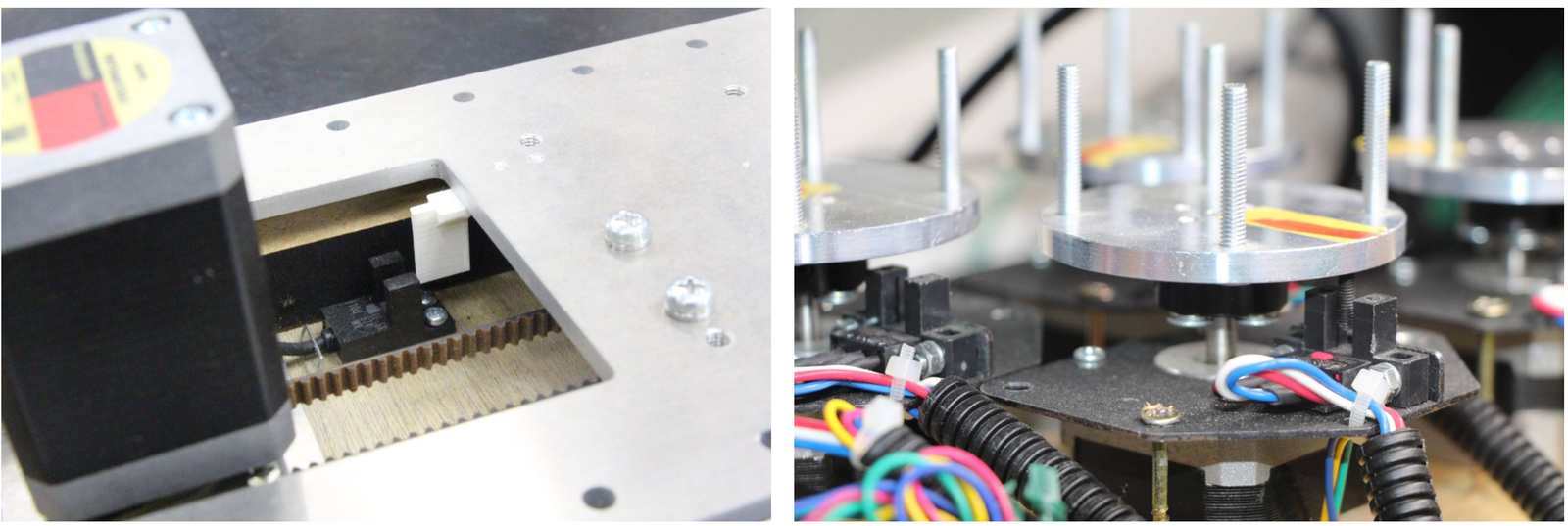
Photointerrupters are often used as home sensors. On the left, a white piece of plastic attached to the slider blocks the photointerrupter's light-emitting and receiving parts. The right side is an example of a rotary table where the photo interrupter responds to the black screw.
Other devices such as microswitches or photoelectric sensors are also used for the sensing.
HOME and LIMIT sensor
Each axis of both the STEP400 and STEP800 has a HOME connector which can connect sensors or switches. The STEP400 has LIMIT sensor inputs in addition to HOME inputs. 5V is supplied to each connector for the sensing power source.
HOME
This input is connected directly to the motor driver chip and can be used in conjunction with the driver's homing function. Usually, this connector is used for the home sensor.
LIMIT (STEP400 Only)
Some applications may require two sensors. For example, a slider has a limited operating range and if it stalls during operation, it may collide with one of either end. In such cases, installing sensors on both ends of the slider will prevent collisions.
The motor can be set to force-stop when these sensors respond, but these can also be used as simple switch inputs separated from the motor operation. For example, you can connect a push button to one of them and press to send an OSC message.
Collision prevention settings
You can limit the motor's rotate direction when the HOME or LIMIT sensors are activated. With the commands /setProhibitMotionOnHomeSw /setProhibitMotionOnLimitSw, you can prohibit the actuator from moving towards homingDirection when the HOME sensor is active, or the reverse direction towards homingDirection when the LIMIT sensor is active. With this, you can prevent the mechanism from colliding with its bounds.
homingDirection can be set with /setHomingDirection or with the Config Tool. This setting is also used for the /homing command.

Homing commands
The homing command is /homing. This command consists of two commands, /goUntil and /releaseSw, which are inherited from the powerSTEP01/L6470 motor driver chip . Let's look closer at those commands.
/goUntil
First, use this command to move towards the home sensor. The motor will decelerate and then stop when the home sensor activates (if it has been set up as such).
-> /goUntil
/releaseSw
This command slowly moves the motor in the opposite direction from the current position and stops immediately when the HOME sensor reading is no longer active. The position where the motor stops is the origin/home position! However, strictly speaking, the /goUntil command does not stop immediately, but stop after deceleration. Its current position has a slight negative offset from the point where the sensor actually responded. This is not accounted for in the firmware as every environment is different.
-> /releaseSw
Both commands can be configured to reset the current position to zero the moment the sensor responds with /setHomeSwMode.
To better illustrate this interaction, here is a demo video.
/homing
It is possible to send above two commands over OSC one after another, however, the /homing command executes this sequence in single operation. It will automatically complete the home sequence according to the homing direction and homing speed which are pre-configured with the Config Tool or with the commands /setHomingDirection and /setHomingSpeed, respectively.
Homing Timeouts
Both /goUntil and /releaseSw have pre-configured timeouts. When either command times out--that is, the HOME sensor's state has not changed after a period of time--the controller will halt the movement of the motor. This is to prevent the moving part from being pushed against other mechanical objects endlessly and for safety.
Normally Open and Normally Closed
Electrical connections
Let's explore "sensor reaction” a little bit more in detail. The pin assignments of HOME and LIMIT connectors are as follows.
| Pin number | Function |
|---|---|
| 1 | GND |
| 2 | Switch/Sensor input |
| 3 | 5V Power Output |
Each sensor pin (2) on HOME and LIMIT is pulled up to 3.3V. To connect the switch, connect the GND (1) and the sensor terminal (2). When the switch is pressed, it is connected to the GND pin and the voltage drops from 3.3V to 0V. When the voltage changes from HIGH level to LOW level (a.k.a. Falling Edge), the sensor is considered to have activated.
Let's take photo interrupter EE-SX671A as an example, where the connection is as follows:
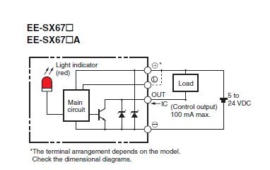
| Pin number | Function | Sensor pin |
|---|---|---|
| 1 | GND | - |
| 2 | Switch/Sensor input | OUT |
| 3 | 5V Power Output | + |
Light or No Light Activation
This is the part you need to consider carefully before ordering a sensor.
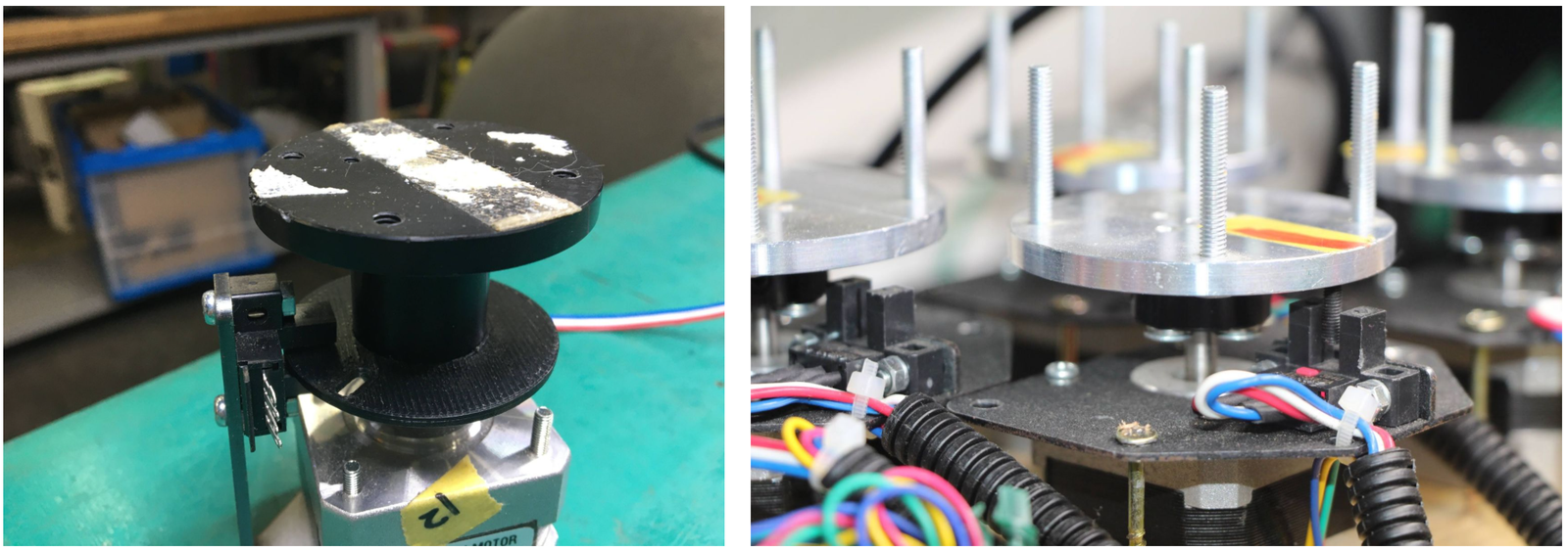
In the case of the left picture, the light enters into the sensor at the home position, but in the picture on the right, the light is blocked at the home position.
There are two types of sensors, one that turns on when light enters and one that turns on when light is interrupted. In the case of the above Omron sensor, the action is toggled by connecting the "L" and "+"" terminals.
The mechanism and sensor must be combined in such a way that the sensor pin goes from HIGH to LOW at the home position.
Rotary Tables
In the left example on the picture above, the response position of the home sensor will differ between clockwise and counterclockwise, depending on the size of the hole. The controller can notify both HIGH to LOW and LOW to HIGH changes of the home sensor by OSC messages. The message also includes the rotation direction, so you can align the home position if you write a conditional sequence for each rotation direction. This reporting can be configured with /enableHomeSwReport.