Usage
Usage
Basically STEP100/200 can be controlled in the same way as STEP400/800. Please reffer to the STEP400/800 tutorial and the command reference.
STEP100 can use the commands of STEP400, and STEP200 can use the commands of STEP800, but since the number of motor axes is different, the range of MotorID changes as follows.
| Model | Corresponding model | Range of MotorID |
|---|---|---|
| STEP100 | STEP400 | 1, 255 |
| STEP200 | STEP800 | 1-2, 255 |
The sample files for the tutorial can be used in the same way, except for the difference in the range of MotorID.
However, there are a number of differences, which will be explained in the following sections.
Start up
Even if you supply motor power to the X-Nucleo board, it will not supply power to the Arduino side, so you will need to supply a logic power separately from the Arduino board's DC jack or USB. Therefore, if the motor power is turned on after the Arduino, the commands sent by the Arduino at startup will not be received by the motor driver and the initialization will fail.
On the other hand, if you supply power to the motor driver side without powering on the Arduino, the state of the Arduino pins will remain indeterminate and there is a possibility that some unexpected behavior will occur.
Also, older Ethernet shields based on W5100 chip frequently fail to reset at startup.
Considering all this, the surefire way to start is as follows.
- Supply the Arduino power
- Supply the motor power
- Press the reset button on the Arduino or Ethernet shield to reboot the whole devices.
In the STEP400/800, both the Arduino and the Ethernet will reliably start if motor power is supplied.
SD card
Many Ethernet shields have an SD card slot, which can be used for initial configuration using the configTool. However, since we do not have a configuration export tool for STEP100/200 at this time, please use the STEP400 config file for STEP100 and the STEP800 config file for STEP200. Setting data that exceeds the number of motors, or LIMIT switch-related settings, etc. will be ignored.
DIP switch
The STEP100/200 firmware forces the ID to be 1. If you want to connect multiple devices to the network, you need to rewrite the ID for each board. There are definitions of each board in boardsDef.h. Rewrite the numbers in the #define ID 1 and compile.
Alternatively, you could insert your own shield further up the X-Nucleo board and solder your own DIP switches to it.In this case, you need to customize the firmware. For example, if you have a 4-digit DIP switch connected to pins A1, A3, A4, and A5, add the following code to the corresponding board definition in boardsDef.h.
    #define HAVE_DIP_SW
    #define DIP_SW_DIGITS   4
    const uint8_t dipSwPin[DIP_SW_DIGITS] = { A1, A3, A4, A5 };
HOME sensor
In STEP400/800, the connector for the HOME sensor is connected to the SW pin of the motor driver IC. In STEP100/200, the sensor can be connected to the SW pin on the X-Nucleo in the same way. This pin is pulled up so when the sensor or switch reponds, the pin should be connected with GND.
STEP100 (X-NUCLEO-IHM03A1)
The red test terminal, labeled TP1 on the X-NUCLEO-IHM03A1, is the SW pin. You will need to solder directly to this terminal to get the wires out.
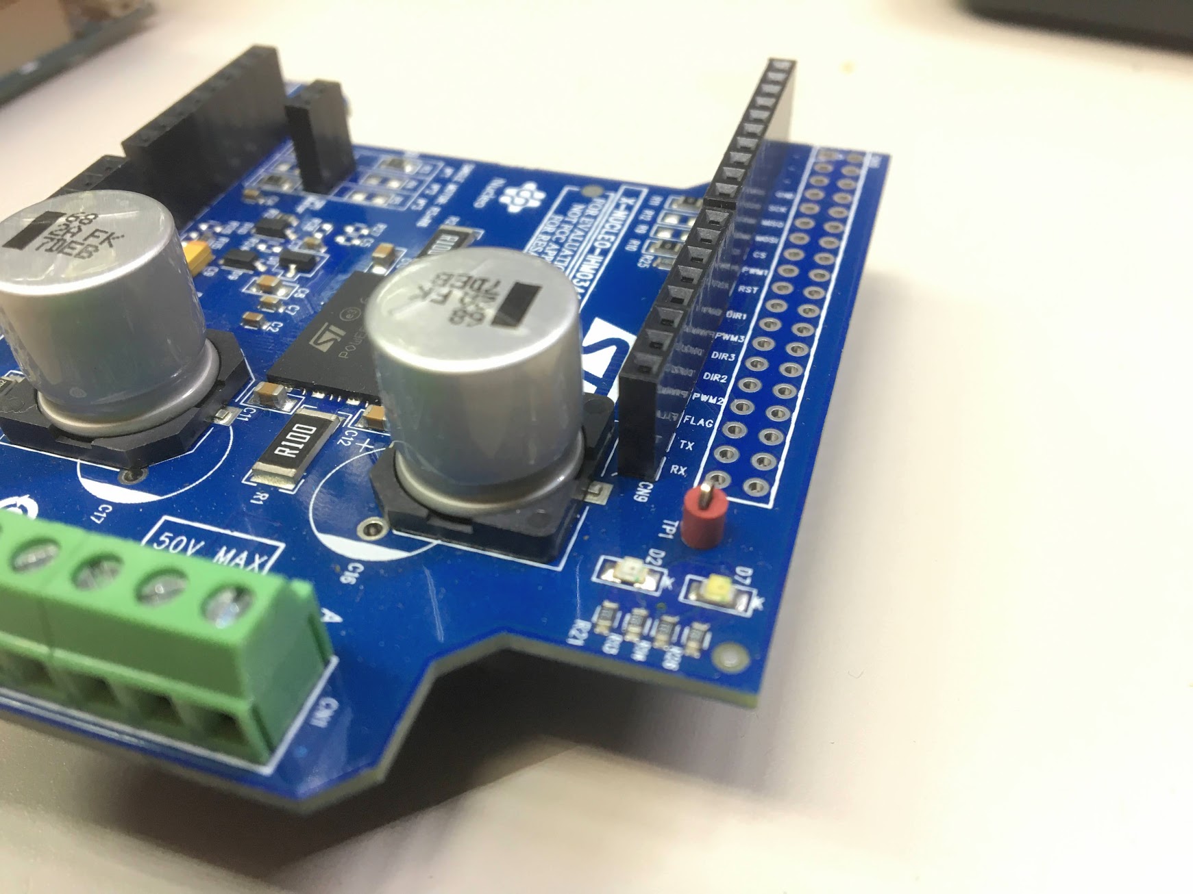
It would be inconvenient to attach the cable from the sensor directly here, so it might be better to put a connector in the middle.
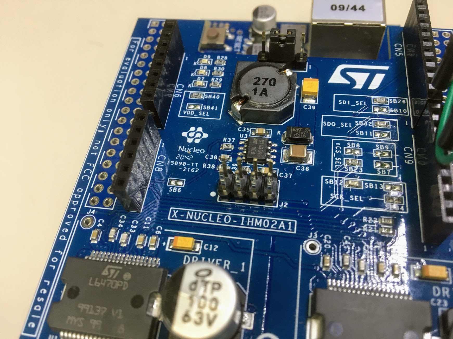
STEP200 (X-NUCLEO-IHM02A1)
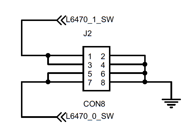
In the IHM02A1, the J2 connector is the SW pin. The white circle (●) on the board represents pin 1 in the circuit diagram.
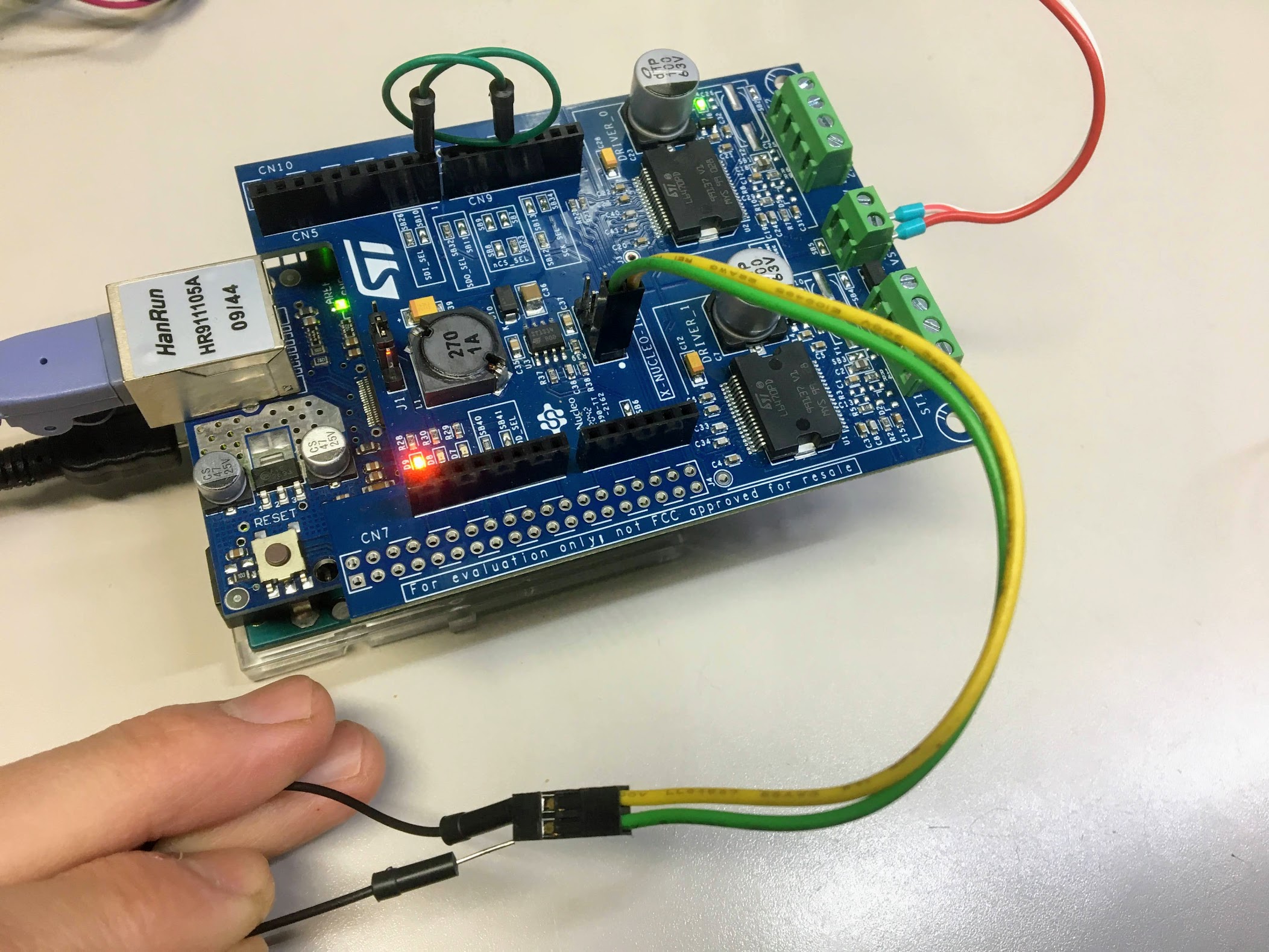
For example, this is how it looks when connected to the SW terminal of the first driver. A jump wire is used instead of a switch to test the functionality.
LIMIT sensor
In STEP100/200, the LIMIT sensor pin is not defined, but it is possible to use an extra pin on the Arduino as a LIMIT sensor. In this case, you need to customize the firmware. Edit the definition of each board in boardsDef.h.
For example, if you add the following definition, you can assign the role of the LIMIT sensor pin to D6 and D7.
    #define HAVE_LIMIT_GPIO
    // In case of STEP100
    const uint8_t limitSwPin[1] = { 6 };
    // In case of STEP200
    const uint8_t limitSwPin[2] = { 6,7 };