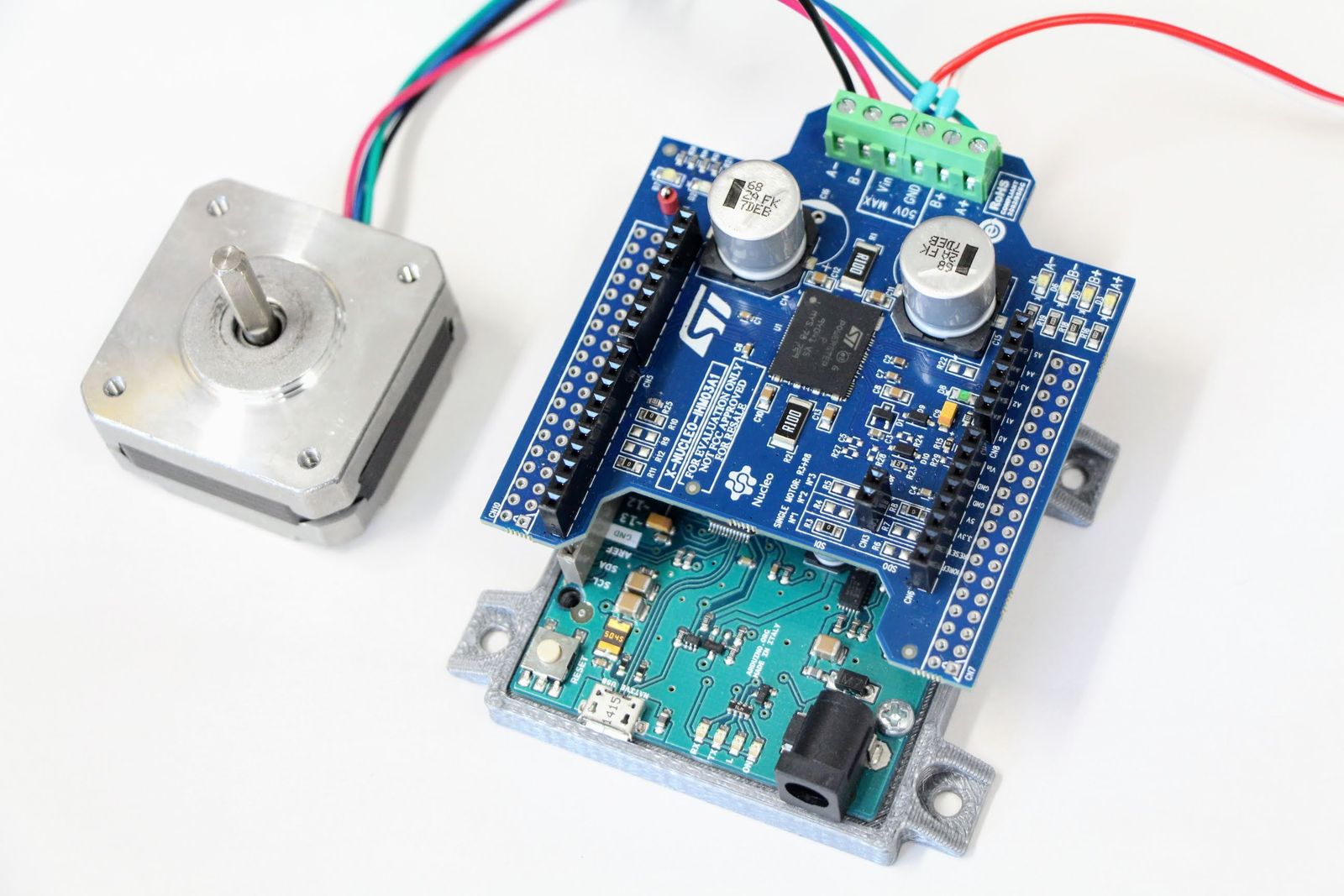
X-NUCLEO-IHM03A1
STEP400 uses a motor driver chip called PowerSTEP01. If you want to try out PowerSTEP01 quickly, the X-NUCLEO-IHM03A1 from STMicroelectronics is a good choice.
This is a board that can be used with STM's Nucleo platform, but it can also be used as an Arduino shield. You can stack up to 3 boards by changing the resistors on each board. You can get it from major electronics distributors such as Mouser or Digikey, with very attractive price!
Try with Nucleo
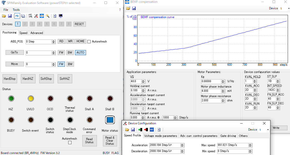
If you have a Nucleo series board, you can use STM's official evaluation tool called STSW-SPIN002: You can use it simply by uploading the provided firmware to Nucleo boards. You can check the register values in detail, which is useful for debugging.
Try with Arduino
You also can test X-NUCLEO-IHM03A1 with the Arduino platform. You can use Megunolink's powerSTEP01 Arduino Library, forked from Sparkfun's AutoDriver Arduino Library. But this library only supports voltage mode, so we present our PowerSTEP01 library, created by further forking this library.
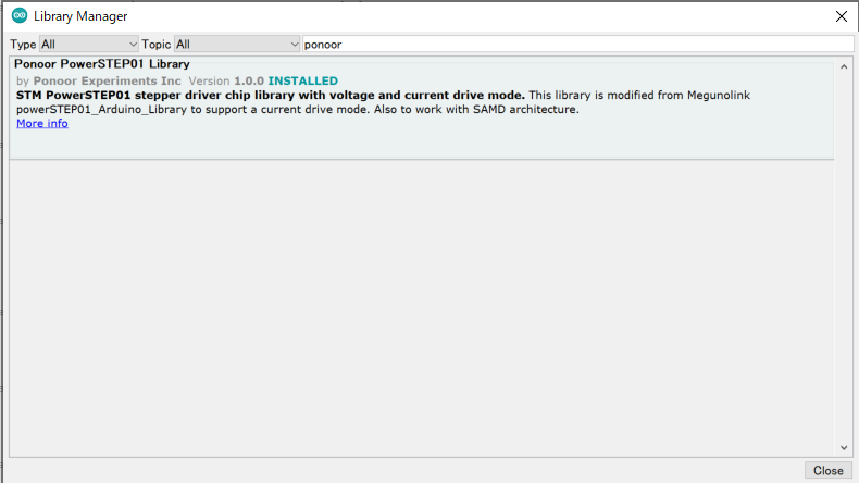
About Ponoor PowerSTEP01 Library
This library has added current mode commands to the original Megunolink library. It also fixes a problem with the SAMD architecture and some register definitions.
https://github.com/ponoor/Ponoor_PowerSTEP01_Library
You can install this library from the Library Manager of Arduino IDE. We have added some more examples including a current mode test.
Notes for using with Arduino
SPI pinouts
X-NUCLEO-IHM03A1 has an Arduino formfactor but the SPI pins are appearing on pins D11-D13, instead of the SPI socket. This is a classic SPI pinout used in Arduino UNO or earlier models, so this shield won't work with other Arduinos like Leonardo/Mega. In Arduino Zero/M0, you can use these pins by configuring them to behave as SPI pins.
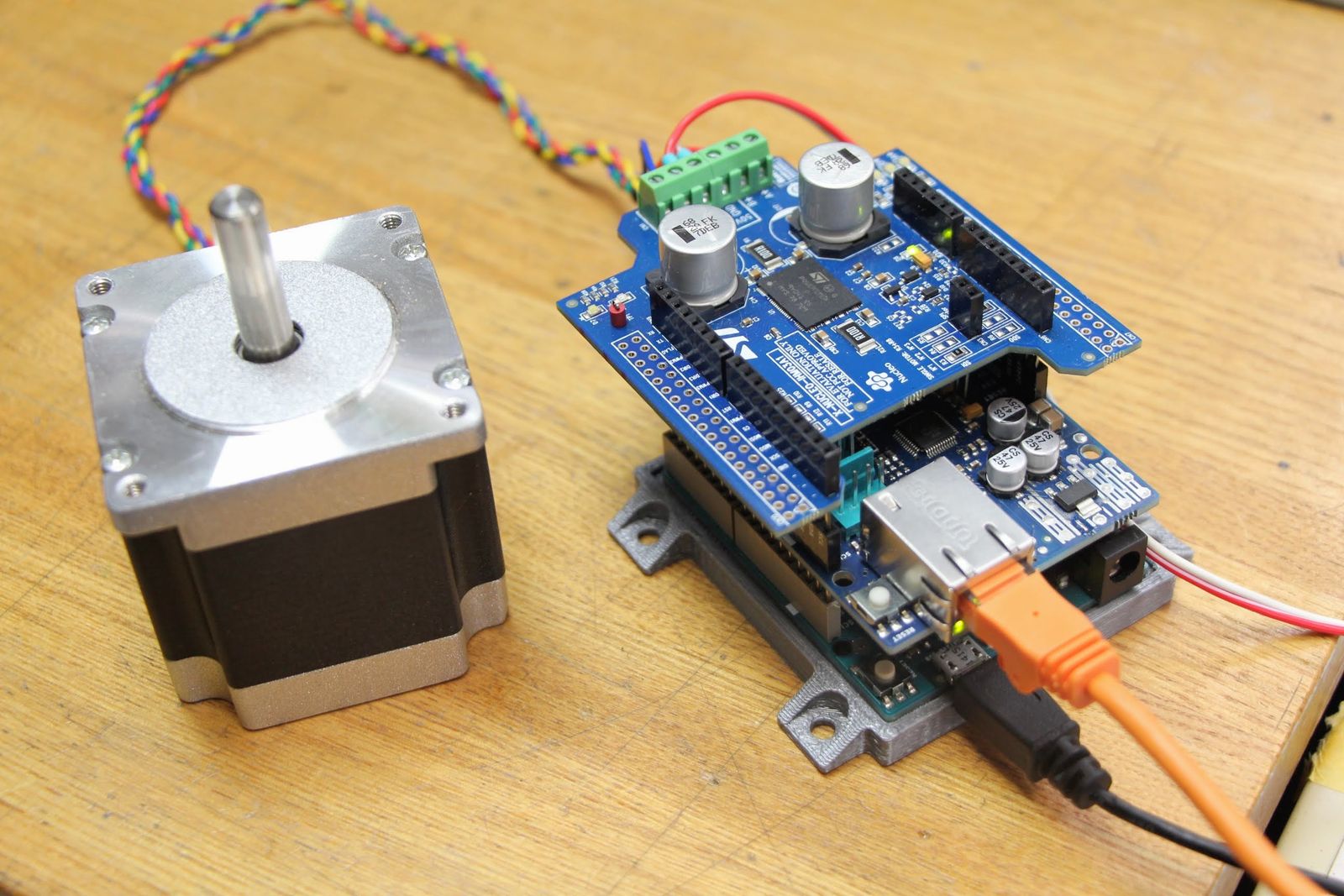
Use with Ethernet shield
Using the X-NUCLEO-IHM03A1 in combination with the Ethernet Shield will provide a ready-to-use system for your project!
But you should be aware of the following points:
- The BUSY pin of PowerSTEP01 is connected to D4 and interferes with the CS pin of the SD card in the Ethernet shield.
- CS pin of PowerSTEP01 is connected to D10 and interferes with the CS pin of the W5500 (or W5100 if dealing with the old type) of the Ethernet shield.
Both of these pins can be replaced with other pins by replacing the jumper resistors on the X-NUCLEO-IHM03A1 board.
Also, the SPI mode is different on the Ethernet shield and PowerSTEP01. Therefore, when you communicate with PowerSTEP01, you must insert this sentence in advance.
SPI.setDataMode(SPI_MODE3);Essentially, this instruction should not be necessary because the mode is set every time SPI communication is done in the library, but for some reason it doesn't work if it's omitted. I'm still investigating the reason.
In STEP400, this process is not required because different SPI ports are assigned to the Ethernet chip (W5500/W5100) and the motor driver (PowerSTEP01) , thanks to the multi SPI ports functionality of the ATSAMD21 chip.