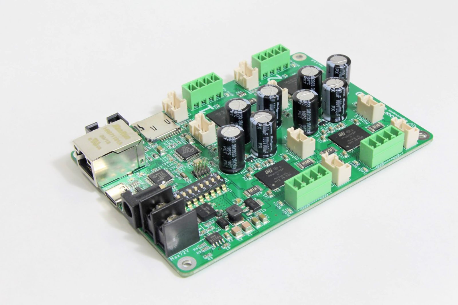
A 4-axis stepper motor driver for creative applications
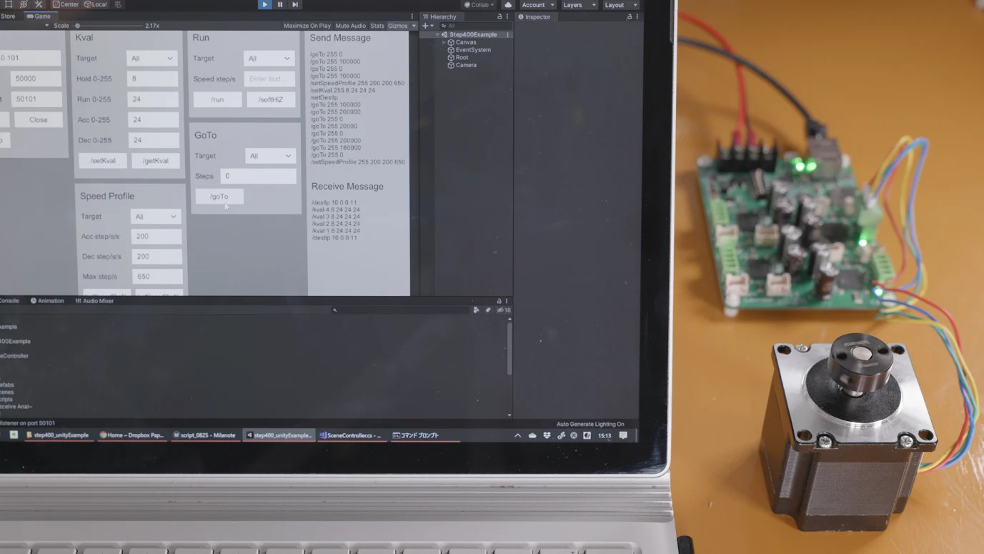
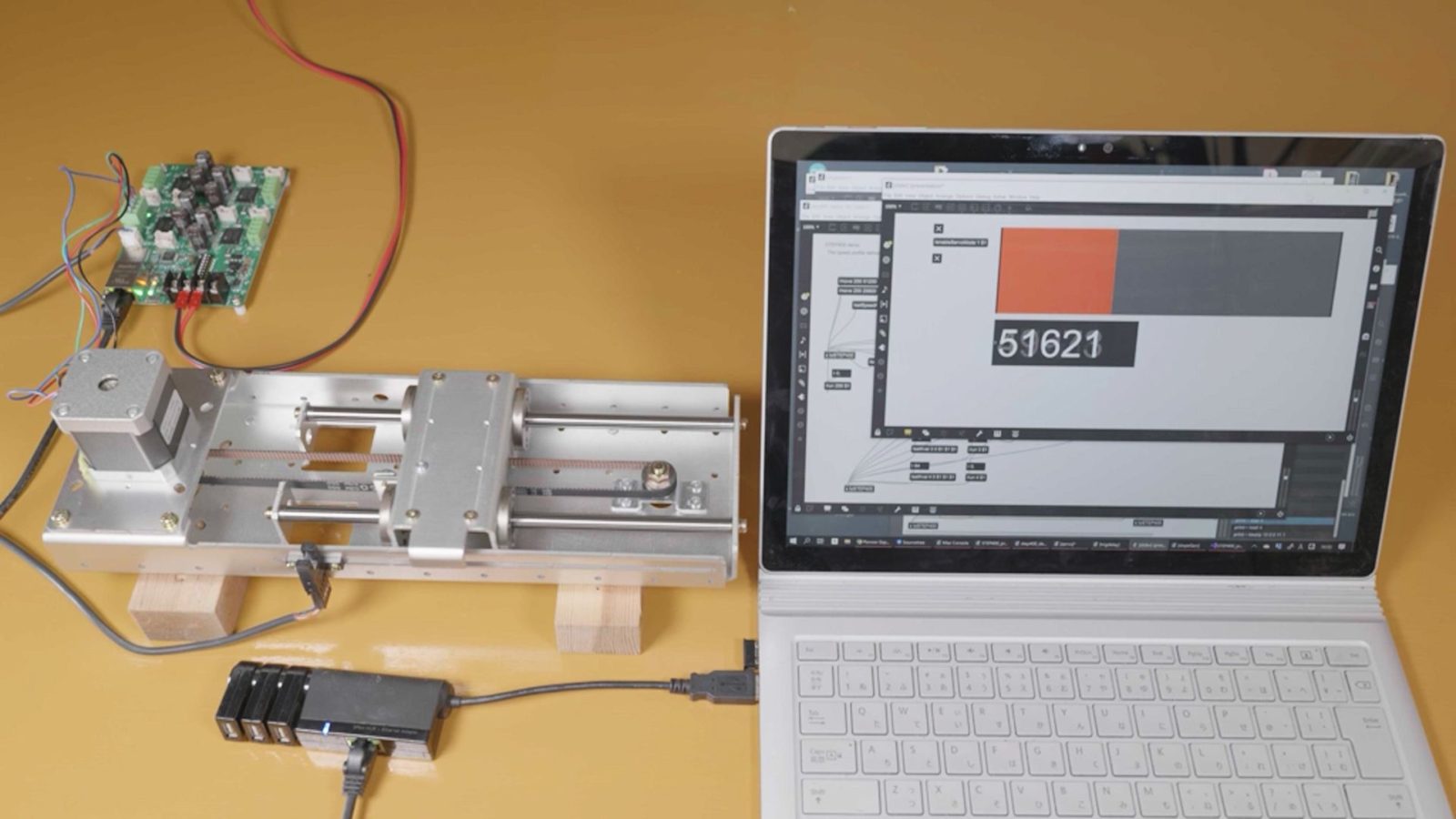
STEP400 is a stepper motor driver board capable of controlling up to 4 axes. STEP400 elegantly combines all the necessary functions, from communication to control, into a simple and complete package. STEP400 uses Open Sound Control (OSC), which based on standard Ethernet rather than a specialized industrial protocols, to achieve ease of use while ensuring that it is reliable enough for use in art, design or any other creative applications. STEP400 can easily controlled by creative coding environments such as openFrameworks, Processing, Max, Unity, and Touch Designer.
We done a crowdfunding project with Crowd Supply and now about to distribute. The campaign was done but you can place your order from them,
Born from the needs of real projects
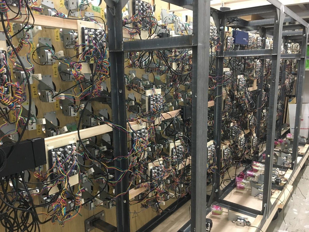
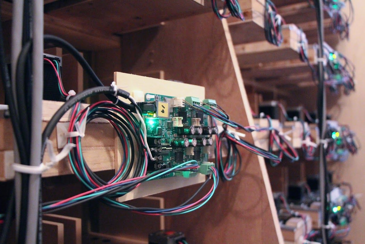
STEP400 comes out of a number of projects we have done with stepper motors. We initially built the system using a combination of DIY modules, but as the system scaled up, the wiring became chaotic, causing all sorts of problems due to the unstable connections between modules and the length of the digital signal path.
After some struggles while working on projects, we realized that we should design a dedicated driver board that would put together everything we needed. Prototypes of STEP400 were created for our own purpose and have been used, tested and validated in a wide variety of real-world projects.
Open Sound Control (OSC) protocol
The standard way of controlling stepper motors is with industrial Ethernet, which lacks compatibility with general network devices as well as open specification. This makes it more time & money-consuming than necessary to use it for any purpose other than factory automation.
Since STEP400 is a stepper motor driver designed specifically for creative applications, it uses the simple and easy-to-use OSC protocol to solve this issue. Open Sound Control (OSC) is an open-ended, dynamic, UDP-based protocol with a URL-style symbolic naming scheme . It is widely used in the field of electronic music and new media art.
Control of STEP400 base on Arduino Zero and Ethernet shield elements. You are free to decide how to control it. For instance, you could rewrite the Arduino sketch to be controlled by Artnet or WebSocket, or by basic USB serial data.
Refer this update for demo videos of OSC control from several programing environments.
Functionality
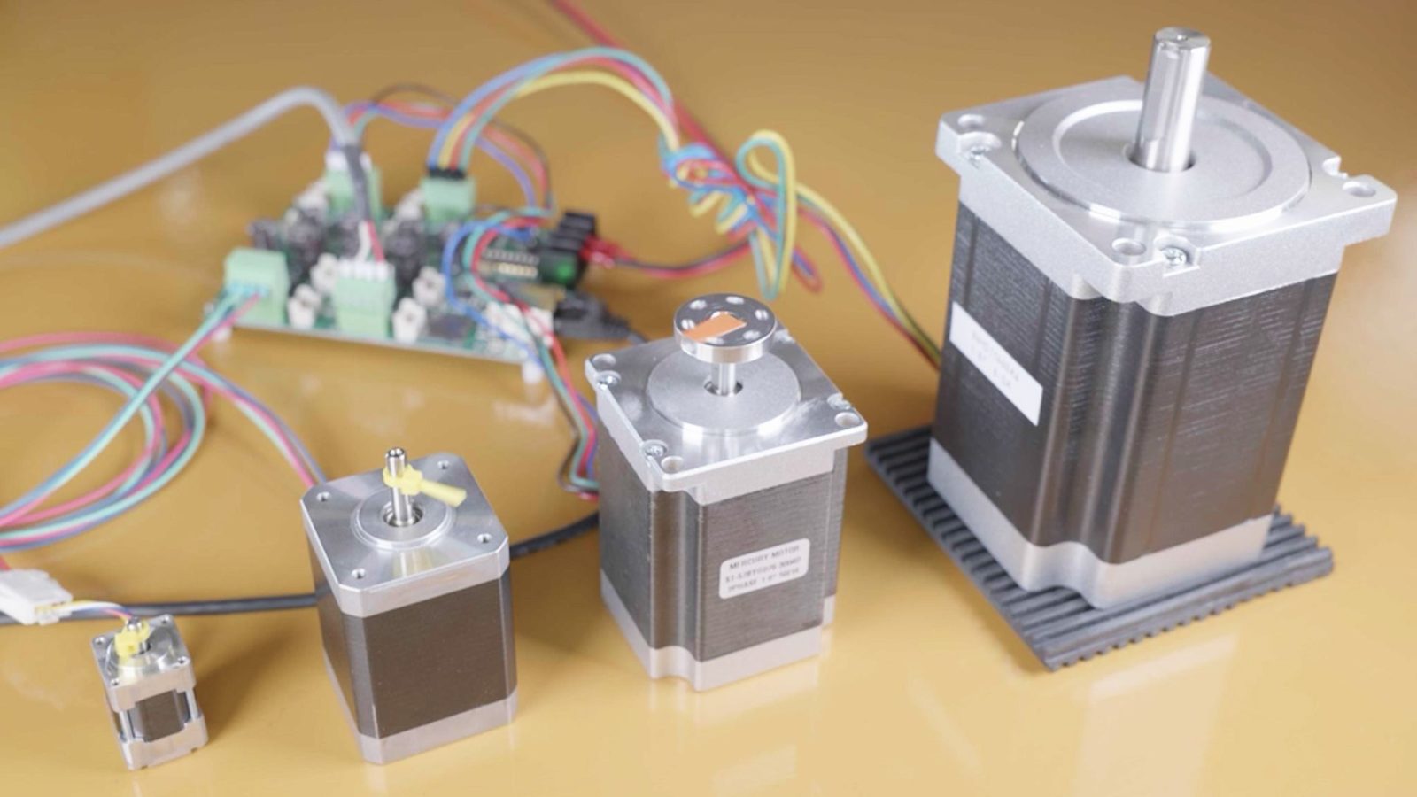
- STEP400 can drive 4 motors, from tiny to high powered ones.
- Two drive modes are available: a smooth and accurate voltage mode, and powerful current mode, which can be used to drive high speeds.
- An open loop servo mode is available to track the target position stream in real time, like an RC servo.
- A simple configuration tool generates a readable JSON file, which can be loaded via a microSD card.
- Ethernet connectivity allows for the system to be easily scaled up.
- Open source hardware and software
Options
Electromagnetic brake board
Sensor cable
Documentation
You can find all source codes and design files from Github repository.
https://github.com/ponoor/STEP400
Specifications
| Applicable motor | Bi-polar stepper motor |
| Axes | 4 |
| Supply voltage | 12V-72V |
| Absolute maximum rating supply voltage | 80V |
| Maximum phase current | 5A/phase |
| PCB dimension | 120mm x 84mm, t=21mm (Including protrusions) |
| Weight | Approx. 80g |
| Apparatus | 4pin connector for a motor x4 |
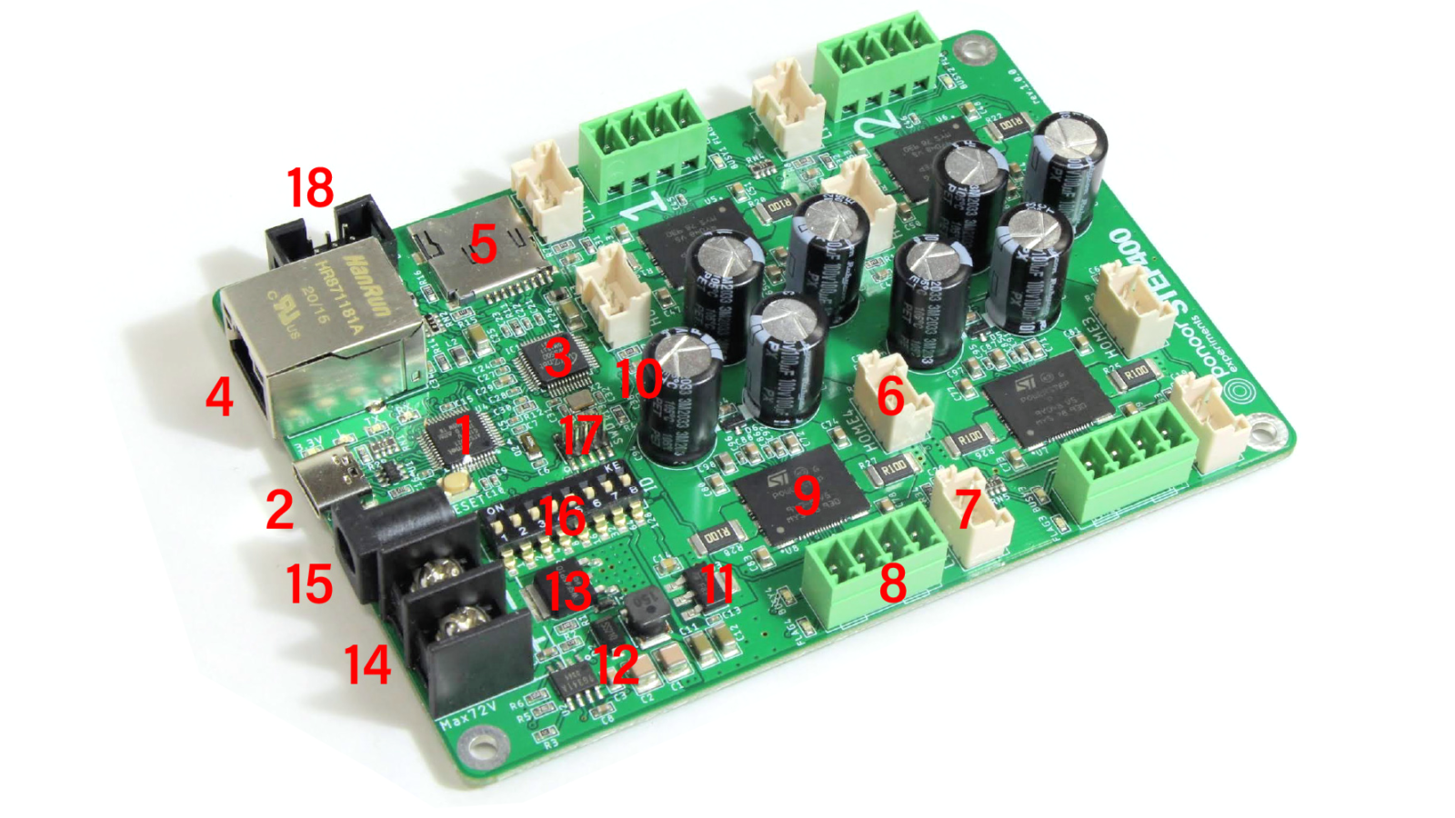
| Number | Description |
|---|---|
| 1 | MCU, Microchip ATSAMD21G18A, Works as Arduino Zero. |
| 2 | USB type-C for the USB connection of the MCU and logic power supply. |
| 3 | Ethernet controller Wiznet W5500 |
| 4 | RJ45 connector with magnetics for Ethernet connection. |
| 5 | microSD card slot. A JSON configuratin file can be loaded from here. |
| 6 | HOME sensor or switch input with 5V power output. JST XA (B03B-XASK-1) |
| 7 | LIMIT sensor or switch input with 5V power output. JST XA (B03B-XASK-1) |
| 8 | 3.81mm pitch Euro style pluggable terminal block for bi-polar stepper motor. |
| 9 | Stepper driver chip, STMicroelectronics PowerSTEP01 |
| 10 | 16MHz crystal oscillator to synchronize all driver’s clock. |
| 11 | 5V to 3.3V LDO |
| 12 | Step down buck converter. Input range : 12V to 75V, output 5V. ROHM BD9G341AEFJ |
| 13 | P-MOSFET for reverse polarity protection. |
| 14 | Power input screw terminal, 3mm screw. Input voltage range : 12-72V |
| 15 | DC jack, 5.5mm/2.1mm, center positive. Connected in parallel with #14. |
| 16 | DIP switch to set ID. |
| 17 | SWD connector to program SAMD chip. |
| 18 | A box header for the add-on brake board, or for general I/O purposes. |
