Tutorial
Example Files
The STEP400 and STEP800 both communicate via the Open Sound Control (OSC) protocol.
A myriad of applications can also communicate with these devices, so example configuration and setup files are provided in the list below:
-
Max (recommended. download Max)
-
Processing (thanks @yuskegoto)
-
openFrameworks (thanks @niimi)
-
Touch Designer (thanks @loveandsheep, @yuskegoto)
-
Node-RED (thanks @yuskegoto)
-
Python library (thanks @JulianOrteil)
Wiring
Communication
Both devices communicate via Ethernet, meaning your computer must have an ethernet port or a USB-ethernet converter. This tutorial will assume you have connected the device directly to your PC (peer-to-peer); however, if this is not possible for you, then plugging the device into a network switch is also viable.
Please plug the ethernet cable in now.
WARNING: Ensure your switch is actually a switch. Do not plug these devices into a router as router ports behave differently than switch ports do.
NOTE: Please do not power the device until directed to do so later in the tutorial. You will be asked to connect the power supply in the upcoming sections, but make sure it is not on.
Stepper motor
Only 4-wire, bipolar stepper motors can be used with these devices. As an example, a highly accessible and inexpensive stepper motor is Mercury Motor's SM-42BYG011-25. This tutorial assumes you are using this motor, so, if you are not, you may need to watch out for specific settings that may need to be changed to match the motor you have. The SM-42BYG011-25 can be purchased from one the (unaffiliated) recommended sites below:
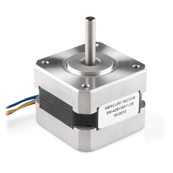
From the wiring diagram found in the datasheet for this motor, we can see that the wiring pairs are Red - Green and Yellow - Blue.

The wiring to the terminal block should look like this:

Power supply
If you want to run a single motor in the example above, the AC adapter’s capacity of 24V1A is sufficient. The power supply must have DC barrel plug with 5.5mm outer diameter / 2.1mm inner diameter / center positive.
NOTE: Again, make sure not to power the device. You may connect the supply, but make sure it is not on.
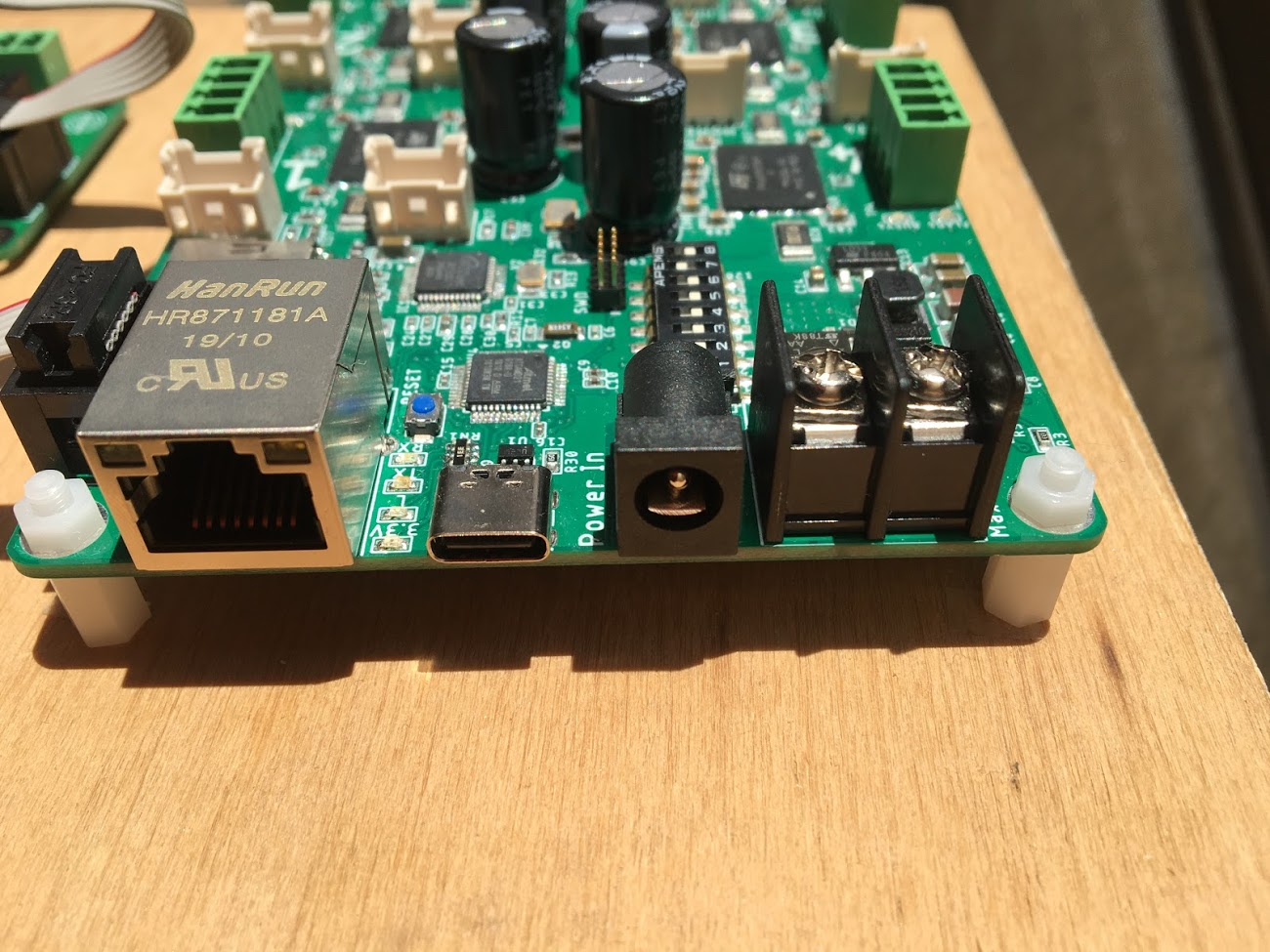
Supplying from the DC barrel jack is sufficient for this size of motor, but if you need to drive much larger motor with high voltage , high current capacity, use the screw terminal block next to the DC jack. See "Power supply and Motor" for details.
Network settings
Configuration Tool
Both devices do have a microSD card slot included on the board. Using this slot, you can just about completely configure the device using our convenient Configuration Tool This tool is a webpage, that can be accessed through your browser--so no third party software is required.
This tutorial uses default settings, so we will not be using the microSD card. Just leave the slot empty.
Dip Switches
The DIP switches on the board must be set to 1. This means only the left-most switch is ON and the rest are OFF. With this configuration, the board has the following network settings:
| Name | Value | Description |
|---|---|---|
| IP address | 10.0.0.101 | The IP address of the device |
| Server address | 10.0.0.10 | The IP address of the server (i.e. your PC) |
| OSC incoming port | 50000 | The port the device is listening on |
| OSC outgoing port | 50101 | The port on the server that the server is listening on |
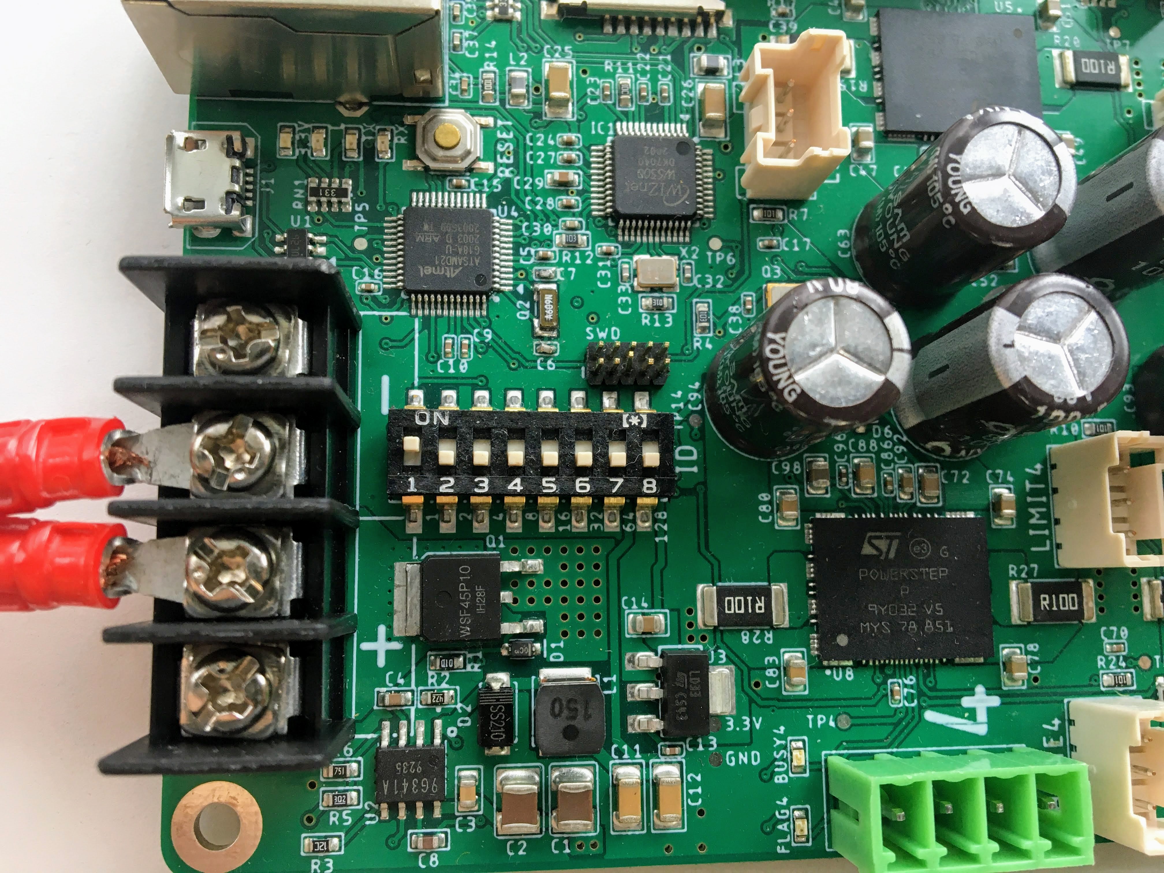
Configured DIP switches on the STEP400.
Now with the motor, power supply, and ethernet cord connected; and the DIP switches set, you may now power-on the device. Please remember the bottom side of the board does have high-voltage and high-current pins, so either place the board on non-conductive material or attach spacers to avoid damaging the board or hurting yourself.
PC Configuration
As seen in the table above, the device will expect your PC (server) to exist at a certain IP address. If you need to, you can set it statically by reviewing the guides linked below:
| Name | Value |
|---|---|
| IP address | 10.0.0.10 |
| Subnet mask | 255.255.255.0 |
Verifying the Connection
After configuring the above settings, you can verify your connection by running ping 10.0.0.101 from your terminal (Command Prompt on Windows).
From this point forward, how you send commands to the device will completely depend on your environment, but we will focus on describing the actual Open Sound Control messages that are sent and received.
Before sending configuration commands to the device, you must first send the command:
/setDestIpThis tells the device where response messages will be sent. Until this command is received by the
device, it will not send any OSC messages beyond /booted. This is because operation may become
unstable if the device continues to send OSC messages to a non-existent destination. You will
receive the following response at the port 50101 from the device if /setDestIp was received without issue:
/destIp (int)destIp[0] (int)destIp[1] (int)destIp[2] (int)destIp[3] (bool)isNewDestIpdestIp[0-3]: Each bytes of destIp (=Your PC's IP address)isNewDestIp: Indicates if the dest ip has changed (1) or not (0).
We are now ready to configure and control the device.
Get the motor running
Let's send the command to run the motor at a desired speed: /run (int)motorID (float)speed.
motorID specifies which motor to run (1-4 on the STEP400, 1-8 on the STEP800). Each ID is
printed on the board for your convenience. Specifying 255 will indicate to run all motors at
your desired speed and is a valid parameter for almost every command requiring motorID.
speed specifies the speed and direction of the motor. The range you can set is from -15625.0 to
15625.0 steps/second. If you're using a motor with 200 steps per revolution, specifying 200.0
will run the motor at 1 revolution per second (RPS). Negative values will run the motor backwards.
For example, to make one revolution per second for a motor connected to connector number 1, the OSC message should look like this:
/run 1 200.Is the motor now slowly spinning? If there is an issue, or you would like to stop it, set the speed
to 0 using the /run command or send:
/hardHiZ 255WARNING: Do not disconnect the motor while it is active and running. This will damage your board.
If everything succeeded, then congratulations! You've successfully ran your first motor. But, you
may have noticed the motor ran a little rough--lots of vibration and possibly noisy. This is where
KVAL (and TVAL) come in.
Setting KVAL
In most cases, the reason for rough operation of a motor is insufficient, or excessive, drive voltage. The KVAL register sets this voltage on a scale of 0-255 where 0 means no voltage (cannot move) and 255 is the same as your supply voltage. So, if you have a 24V supply, the motor will run on 24V at 255, or 12V for 128, and so-on.
Each parameter in the /setKVAL command has a unique function.
| KVAL name | Description | Initial value |
|---|---|---|
| KVAL_HOLD | Holding KVAL | 0 |
| KVAL_RUN | Constant speed KVAL | 16 |
| KVAL_ACC | Acceleration KVAL | 16 |
| KVAL_DEC | Deceleration KVAL | 16 |
Let's adjust these values while the motor is running. Send following message to rotate the motor:
/run 1 200.You can set individual KVAL parameters using commands like /setRunKval, but we are going to set all 4 parameters at once. Let's set holdKVAL to 0 and then gradually increase each of the other three simultaneously. To do this, send the command:
/setKval 1 0 24 24 24The syntax of the command is /setKval (int)motorID (int)holdKVAL (int)runKVAL (int)accKVAL (int)setDecKVAL.
This message specifies the first motor's holdKval as 0 and the rest at 24 (approximately 9% of your power supply voltage). Gradually increase the values until the motor begins to turn quietly.
For example: /setKval 1 0 32 32 32, then /setKval 1 0 40 40 40, etc.
As you increase each parameter, the motor's torque will also increase; however, the motor will also begin to vibrate more and produce more heat. Be sure to set the parameters appropriately for your load.
TIP: Remember: we've already calculated configuration files for a variety of motors for you if you would like to use them.