Diagnosis via USB serial port
Diagnosis tool
Overview
You can connect your PC and the deice with USB and monitor status or check the setting. It is practical for trouble shooting, like when you cannot reach the controller over Ethernet network.
Connection
Connect the device and your PC with USB Type-C cable. Only the microcontroller and its peripheral will be powered from USB. In this state, the motor drivers are not powered up, so you cannot communicate with them. Therefore make sure to supply motor power source as well.
Also, be aware that if you fist connect USB cable and then connect motor power, the controller may exhibit unexpected behavior, since the motor drivers will be in uninitialized state. So power the motor power supply first and then connect the USB, or reset the controller by pushing RESET button after powering up motor power.
Serial monitor
The device report itself as virtual serial port to PC and is recognized as Arduino Zero. If you would like to use Arduino IDE serial monitor, the process looks as follows. You can use any serial port terminal client that can send and receive text strings.
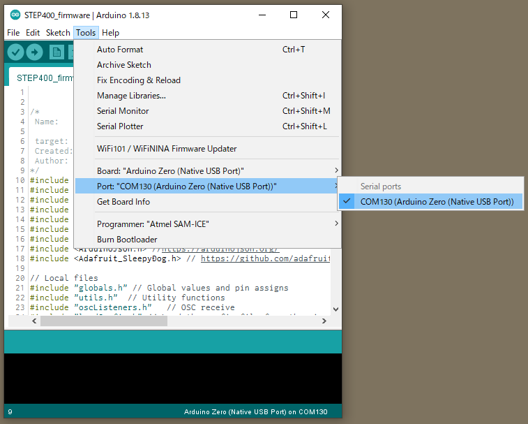
Selecting Port
From Tools -> Port. Find "Arduino Zero (Native USB Port)" and select it.
Open Serial Monitor
By clicking the magnifying glass icon, the serial monitor window will pop up. 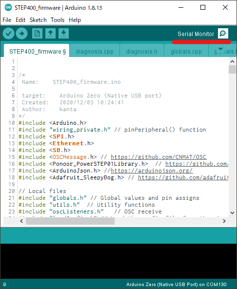
List the menu
From the textbox on the top, enter m and press Send button (or press Return key) you will receive diagnosis menu if the connection is established without issue. 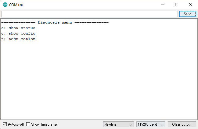
We are going to look through these three items.
Status
By sending s, you can retrieve its hardware status.
Firmware
============== Current Status ==============
-------------- Firmware --------------
Firmware name : STEP400
Firmware version : 1.0.0
Compile date : Mar 19 2021, 10:27:55
Applicable config version : 1.0
Loaded config version : 1.0 [CONFIG_VERSION_APPLICABLE]
This section includes, mainly the firmware information on the chip.
Loaded config version: Shows the config.txt version number read from microSD. Depending on the version of config and firmware, you will get one of the following message.
| Message | Description |
|---|---|
| CONFIG_VERSION_UNDEFINED | Undefined config version |
| CONFIG_VERSION_NOTLOADED | The config could not read from microSD |
| CONFIG_VERSION_OLD | The config version is old |
| CONFIG_VERSION_APPLICABLE | The version of config and firmware matched |
| CONFIG_VERSION_NEW | The config file's version is newer than firmware (Firmware old) |
DIP Switch
-------------- DIP Switch --------------
BIN : 0000 0001
DEC : 1
Shows the status of ID switches on the PCB.
BIN: Shows the switch position as 0/1. Please be aware that the smallest bit comes to the left on the PCB, while it comes to right in the diagnosis tool.DEC: ID number in decimal.
Ethernet
-------------- Ethernet --------------
Ethernet hardware status: 3 -EthernetW5500
Ethernet link status: 2 -LinkOff
isDestIpSet : No
Ethernet hardware status: Shows the connection status of the Ethernet controller IC W5500. If it is working correctly, the message shows its nameEthernetW5500, and ifEthernetNoHardwareis displayed, there is an issue for the communication with WS5500.Ethernet link status: Shows Ethernet link status.
| Link Status | Description |
|---|---|
| LinkON | Linked |
| LinkOff | Unlinked |
| Unknown | Unable to retrieve the status |
isDestIpSet: Shows if thedestIpis set.Yesif the command/setDestIpwas sent already and the controller is able to respond over OSC, in other casesNo.
microSD
-------------- microSD --------------
SD library initialize succeeded : Yes
SD config file open succeeded : Yes
SD config JSON parse succeeded : Yes
SD library initialize succeeded:Noif microSD card is not inserted.SD config file open succeeded: Shows if theconfig.txton the SD card is succesfully opened.SD config JSON parse succeeded: Shows if the content ofconfig.txt(JSON) was read correctly.
Motor Driver
STEP400
-------------- Motor Driver --------------
PowerSTEP01 SPI connection established : Yes
PowerSTEP01 ID#1
    STATUS: 0xE603
    High impedance state : Yes
    BUSY : No
    Motor direction : Reverse
    Motor status : Stopped
    UVLO (Undervoltage lock out) : No
    Thermal status : Normal
    OCD (Overcurent detection) : No
    Stalled : No
    SW_F: 0 -HOME senser input open.
    ADC_OUT: 31 -LIMIT senser input open.
PowerSTEP01 SPI connection established: Shows if the communication with the PowerSTEP01 was established. IfNo, the motor power might be switched off.- Following message will be displayed only if the communication was successful. For messages, #1-#4 will be listed.
STEP800
-------------- Motor Driver --------------
L6470 SPI connection established : Yes
L6470 ID#1
        STATUS: 0x7E03
        High impedance state : Yes
        BUSY : No
        Motor direction : Reverse
        Motor status : Stopped
        UVLO (Undervoltage lock out) : No
        Thermal status : Stopped
        OCD (Overcurent detection) : No
        Stalled : No
        SW_F: 0 -HOME senser input open.
L6470 SPI connection established: Shows if the communication with the L6470 was established. IfNo, the motor power might be switched off.- Following message will be displayed only if the communication was successful. For messages, #1-#8 will be listed.
Modes
-------------- Modes --------------
Servo Mode :  No, No, No, No
Current Mode :  No, No, No, No
Electromagnetic Brake Enable :  No, No, No, No
Brake status :
#1 : BRAKE_ENGAGED
#2 : BRAKE_ENGAGED
#3 : BRAKE_ENGAGED
#4 : BRAKE_ENGAGED
Homing status : 0, 0, 0, 0
Brake status
| Brake status | Description |
|---|---|
| BRAKE_ENGAGED | Brake engaged status |
| BRAKE_DISENGAGE_WAITING | In transition to brake release |
| BRAKE_DISENGAGED | Brake released |
| BRAKE_MOTORHIZ_WAITING | In transition to brake engage |
Homing status
| Number | Homing status | Description |
|---|---|---|
| 0 | HOMING_UNDEFINED | Not homing yet |
| 1 | HOMING_GOUNTIL | Moving towards sensor |
| 2 | HOMING_RELEASESW | Leaving from sensor active area |
| 3 | HOMING_COMPLETED | Homing completed |
| 4 | HOMING_TIMEOUT | Time out was detected while homing |
Config
You can retrieve current settings if you send c. Be aware that this is not the content of the configTool file, but the current setting that reflected actual ID switch setting and other settings over OSC messages. For example if you boot the STEP400 without microSD inserted, following message will show up.
============== Configurations ==============
-------------- Config file --------------
SD config file open succeeded : No
SD config file parse succeeded : No
configTargetProduct : ---
configName : Default
config version : -1.0 [CONFIG_VERSION_NOTLOADED]
-------------- Network --------------
My Ip : 10.0.0.101
isMyIpAddId : Yes
Dest Ip : 10.0.0.10
DNS : 10.0.0.1
Gateway : 10.0.0.1
Subnet mask : 255.255.255.0
MAC address : 60:95:CE:10:05:01
isMacAddId : Yes
inPort : 50000
outPort : 50101
isOutPortAddId : Yes
bootedMsgEnable : Yes
isDestIpSet : No
reportErrors : Yes
-------------- Report & Alarm --------------
reportBUSY :  No, No, No, No
reportBUSY :  No, No, No, No
reportHiZ :  No, No, No, No
reportHomeSwStatus :  No, No, No, No
reportLimitSwStatus :  No, No, No, No
reportDir :  No, No, No, No
reportMotorStatus :  No, No, No, No
reportSwEvn :  No, No, No, No
reportUVLO :  Yes, Yes, Yes, Yes
reportThermalStatus :  Yes, Yes, Yes, Yes
reportOCD :  Yes, Yes, Yes, Yes
reportStall :  Yes, Yes, Yes, Yes
reportOCD :  Yes, Yes, Yes, Yes
OCThreshold : 15, 15, 15, 15
-------------- driverSettings --------------
homingAtStartup :  No, No, No, No
homingDirection(1:FWD,0:REV) : 0, 0, 0, 0
homingSpeed : 50.00, 50.00, 50.00, 50.00
homeSwMode : 1, 1, 1, 1
prohibitMotionOnHomeSw :  No, No, No, No
limitSwMode : 1, 1, 1, 1
prohibitMotionOnLimitSw :  No, No, No, No
goUntilTimeout : 10000, 10000, 10000, 10000
releaseSwTimeout : 10000, 10000, 10000, 10000
microStepMode : 7, 7, 7, 7
isCurrentMode :  No, No, No, No
slewRate : 5, 5, 5, 5
electromagnetBrakeEnable :  No, No, No, No
brakeTransitionDuration : 100, 100, 100, 100
-------------- speedProfile --------------
acc : 1000.00, 1000.00, 1000.00, 1000.00
dec : 1000.00, 1000.00, 1000.00, 1000.00
maxSpeed : 650.00, 650.00, 650.00, 650.00
fullStepSpeed : 15610.00, 15610.00, 15610.00, 15610.00
-------------- Voltage mode --------------
kvalHold : 0, 0, 0, 0
kvalRun : 16, 16, 16, 16
kvalAcc : 16, 16, 16, 16
kvalDec : 16, 16, 16, 16
intersectSpeed : 1032, 1032, 1032, 1032
startSlope : 25, 25, 25, 25
accFinalSlope : 41, 41, 41, 41
decFinalSlope : 41, 41, 41, 41
stallThreshold : 31, 31, 31, 31
lowSpeedOptimize : 20.00, 20.00, 20.00, 20.00
-------------- Current mode --------------
tvalHold : 0, 0, 0, 0
tvalRun : 16, 16, 16, 16
tvalAcc : 16, 16, 16, 16
tvalDec : 16, 16, 16, 16
fastDecaySetting : 25, 25, 25, 25
minOnTime : 41, 41, 41, 41
minOffTime : 41, 41, 41, 41
-------------- Servo mode --------------
kP : 0.06, 0.06, 0.06, 0.06
kI : 0.00, 0.00, 0.00, 0.00
kD : 0.00, 0.00, 0.00, 0.00
Test Motion
All motors will rotate 25600 steps forward by sending t. This is equivalent to one rotation for the 200 steps stepping motor controlled with 1/128 microsteps.