Power supply and Motor
Connecting a power supply
Power supply
The STEP400 and STEP800 both have differing power ratings. These devices also have two different power input terminals. While the USB-C jack can be considered a power input terminal, it's primary, and arguably sole purpose, is to provide USB communication. By design, the USB protocol can only supply of maximum of 5V which is not enough to fully power the board. It is, however, safe to power both devices through either primary input (4 and 5 in the picture below) and have USB connected, but do not connect power to both primary inputs.
Terminal for the power supply
There are 2 types of power input terminals on this device, a DC jack (4) and a screw terminal(5).
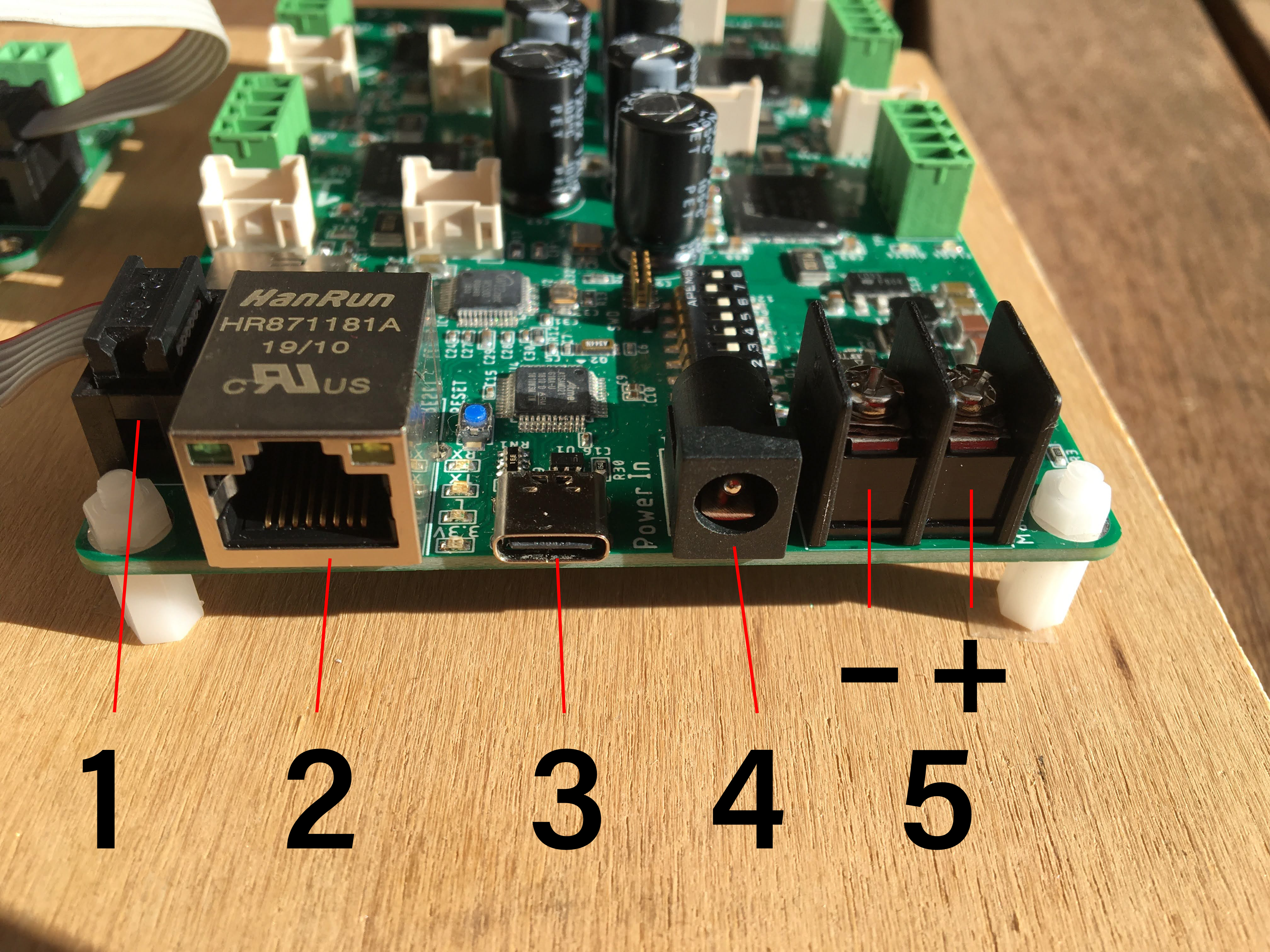
| Number | Description |
|---|---|
| 1 | Connector for the electromagnetic brake (STEP400) |
| 2 | Ethernet |
| 3 | USB type-C |
| 4 | (Primary Power Input) DC Barrel Jack |
| 5 | (Primary Power Input) Screw Terminal |
WARNING: Again, do NOT connect both 4 and 5. This will damage your controller.
As stated above, both devices have different power ratings and different ratings for each primary input.
| Controller Board | Max Power Rating | Barrel Jack | Screw Terminal |
|---|---|---|---|
| STEP400 | 12V-76V @ 20A | 24V @ 5A | 76V @ 20A |
| STEP800 | 9V-36V @ 16A | 24V @ 5A | 36V @ 16A |
The amps listed here reflect the cumulative maximum phase current draw of all motors, not the maximum current capacity of the power supply. Look at Current Capacity for more information. The STEP800 has a maximum phase current draw of 2A per motor whereas the STEP400 has a maximum of 5A. Please keep these limits in mind when choosing your motor.
DC Barrel Jack
The DC barrel has the following specifications beyond its power rating:
- 5.5mm outer diameter
- 2.1mm inner diameter
- Center positive
Screw Terminal
The screw terminal has the following specifications beyond its power rating:
- Negative left side, positive right side
- M3 screw diameter
- Use a wire terminal like the
NICHIFU TMEX1.25-3Nfor a more secure connection
Motor connection
Motor Selection
This device can be used with bipolar stepper motors, and it's phase current is depended on the products;
| Product | Phase Current |
|---|---|
| STEP400 | 5A or less |
| STEP800 | 2A or less |
We have calculated register values for some motors based on our actual measurements and made them available in the form of configuration files. They can be found from following URL:
https://ponoor.com/en/docs/step-series/settings/example-parameter-values-for-example-steppers/
Terminal for motors
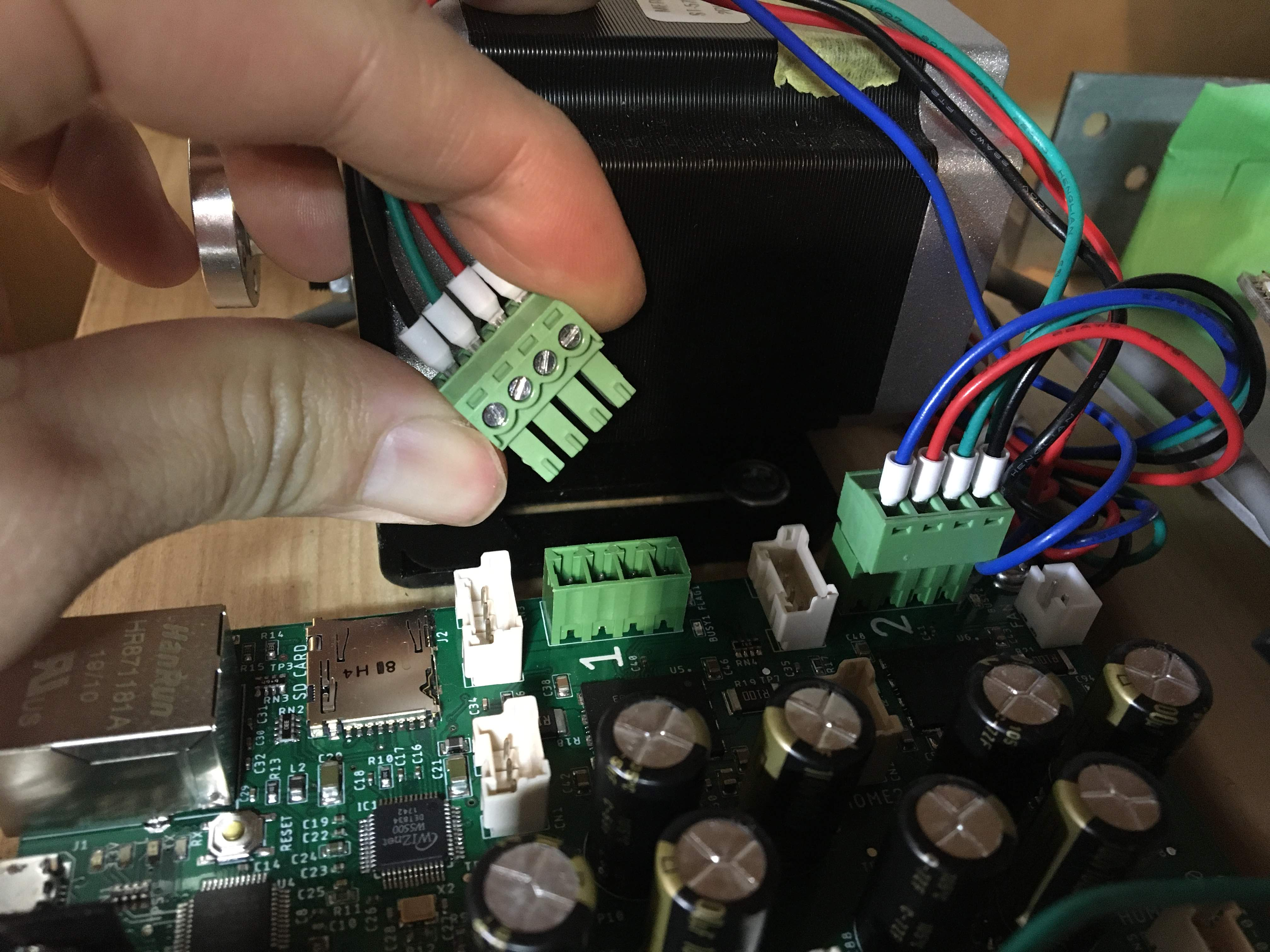
A 3.81mm (0.150") pitch header (Euro-style terminal block) is provided on the board. Corresponding connectors include following:
- TE Connectivity AMP Connectors 284507-4
- Ningbo Kangnex Elec WJ15EDGK-3.81-4P
The bipolar stepping motors has two coils. To connect the motor to the STEP400, we need to figure out which of the four wires from the motor are wired to which coil. The combination of wire color and corresponding coil is described on the data sheet. If you have a multimeter by your side, you can determine which wires are connected to the same coil, as the resistance of the coil is very low. Connect the wires from two coils as follows.
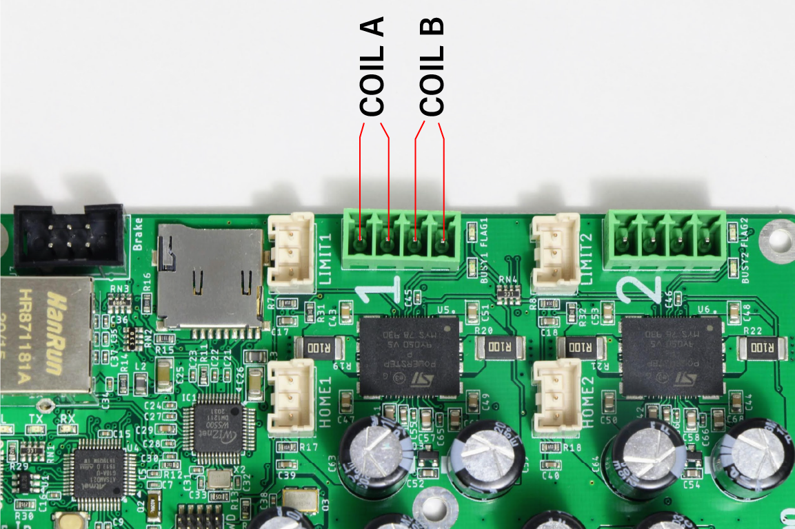
It is not crucial which coil is the coil A or B on this picture. It does also not matter how the wiring order is. It won't affect the motor itself if these wirings are inverted, however the rotation direction will change. For the practice it is recommended to have a common wiring rule.
The Relationship Between Power Supply and Stepper Motor Ratings
Inductance
The copper windings inside a stepper motor behave as an inductor. When power is supplied to the inductor, current rises gradually--it is not instant. Stepper motors that operate through the ON/OFF cycle see decreased current the faster they move because the current cannot reach its maximum. Because the motor's torque is virtually proportional to it's phase current, that means higher speeds means lower torque.
Power supply voltage
To overcome the inductance and let driving current into the motor, you need to use a power supply with high voltage as possible. If you look at the motor’s datasheet, you might see very low rating voltage, but when you drive the motor, it will not be able to deliver the required current at that voltage. In fact, you will need to supply voltage several times higher.
Following graph from ST's application note is an example that shows the relation between supplied voltage and current. Actual value may vary depending on the motors, but we can see that the driver cannot supply enough current as the rotation increases when using a power source with low voltage.
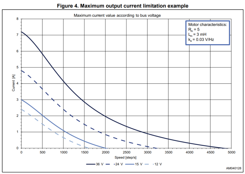
The required voltage varies greatly depending on the motor's rating, required speed, and required torque. But, in general, the required voltage is roughly as follows:
- Until NEMA17 size : 24 V
- NEMA23 or bigger : 48 V or 72 V for high speed
This means the STEP800 may not be suitable for driving larger motors; however, some motors may produce high torque in a small form factor and vice versa with a large form factor. It's imperative you review your motor's voltage and current ratings.
The STEP400 does work with a minimum of 12V; however, since that is its on-board DC-DC converter's minimum required voltage, there may be cases where the STEP400 resets on a slight voltage drop. This is especially the case during a motor's inrush current, therefore we do not recommend a 12V power supply unless if you are driving a small motor at a low load.
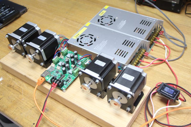
A STEP400 being supplied 48V through two 24V power supplies in series.
Current Capacity
The current capacity of the power supply is as equally important as its voltage. If a motor stalls it may draw a high amount of current that may exceed the capacity of the power supply. This will cause the overload protection circuit on the supply to trigger (if there is one) forcing the supply to shut down. Typically, you will likely need to only supply a few amps to drive small motors at low speeds. But large motors at high speeds often do require high voltage with high current (especially if they are under load). Depending on the quantity of motors, their usecases, as well as your circuit protection settings, we recommend a supply with at least 10A-20A capacity.